
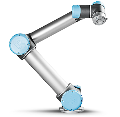
This is an undergraduate research project done in affiliation with the MIT Center for Bits and Atoms(CBA). The goal of this research is to leverage existing technology, 6 degree of freedom robotic arms, to automate the assembly of ultra-performance materials/mechanisms. This page is going to step through the process of me learning to use a specific model of 6 D.O.F arms, UR10 robot arms, to automate assembly.
Getting Started:
My knowledge on how to operate a 6-axis robot arm is non-existent at this point. Fortunately, I found an online tutorial that gives the basic rundown of how the robot arms function. The tutorial provides useful information about the different motion types the robot can execute as well as details on connecting peripheral devices (this will be useful later down the road). The utility of the tutorial, however, is limited in that it strictly uses the teaching pendant as the means for programing the robot.
Movement:
The motions for the arm are characterized as such:
Using what I learned from the online tutorial, I was able to program a path via the teaching pendant. This small success while encouraging is only marginally useful because the motion path is described by a series of remembered position. As I execute the program the arm is traversing through waypoints that I physically moved the end effector to. The next step will be to move on to script programming. There are a surprising amount of resources online for this including Zacobria and an online manual found by Sam Calisch, one of the grad students in the lab. I am also using Sam's previous work as a reference.
Script Programming
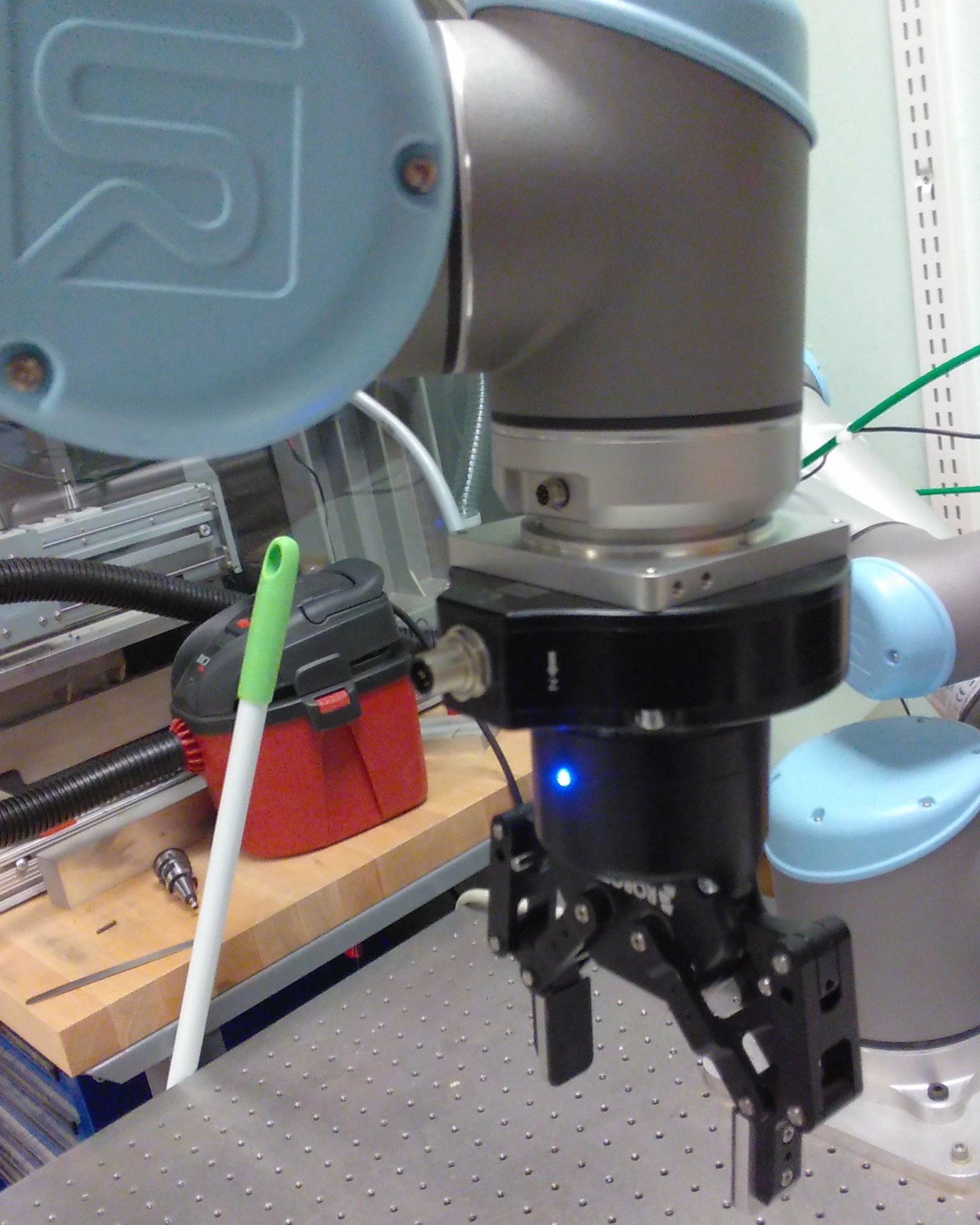
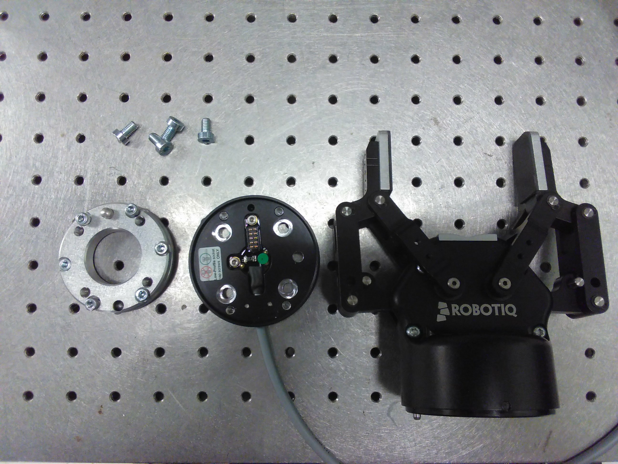
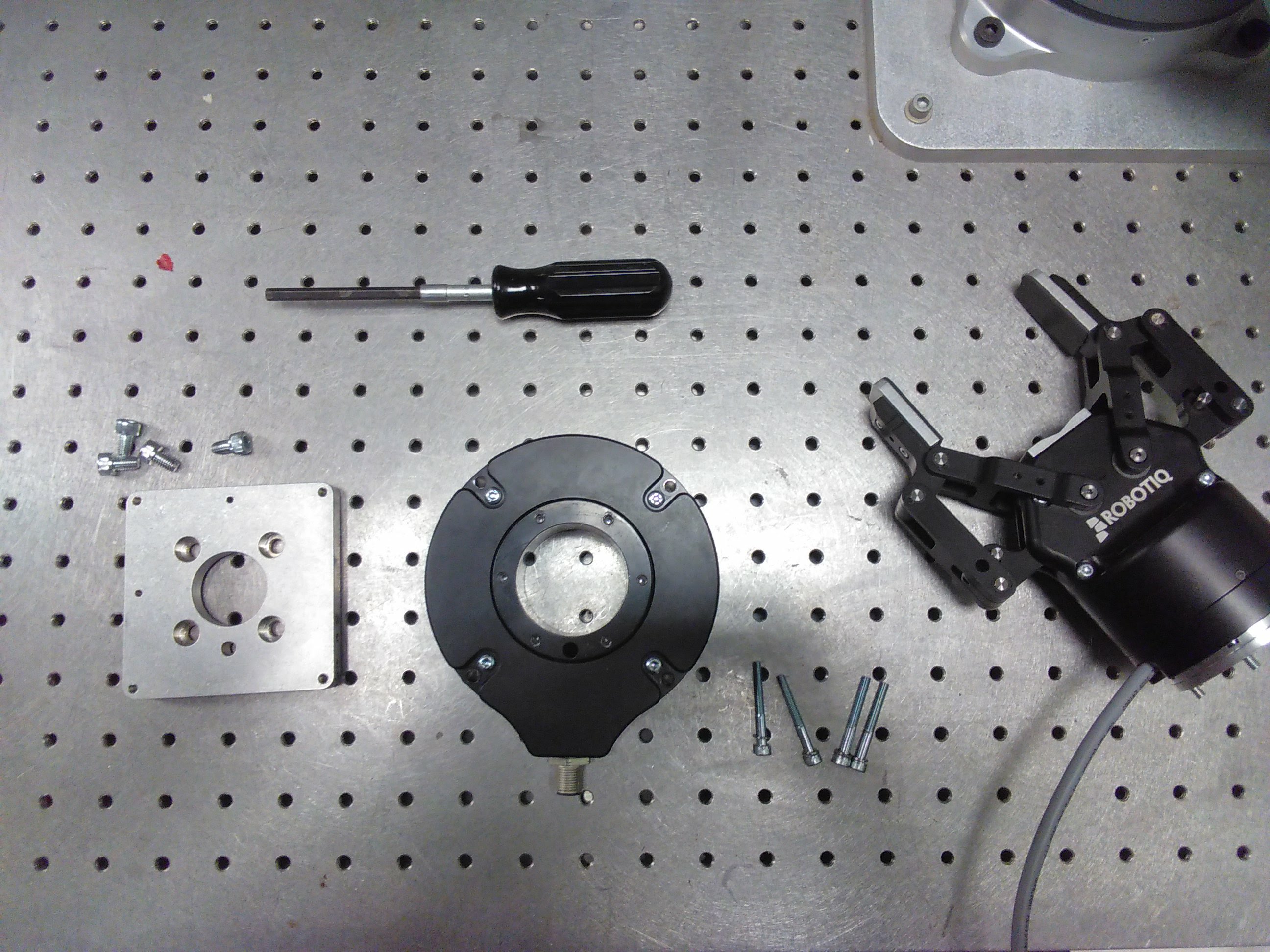
Before working on routines for the arm to run through I wanted to figure out a little more about manipulating end effectors. Conveniently, we have a Robotiq Two-Finger Gripper. It took me more time than I'd like to admit to figure out how to attach this thing 😒. BUT, once I got it attached, controlling the gripper was as simple as a clicking a button on the teaching pendant. Controlling the gripper through the terminal is slighthly more involved. I downloaded a library that handles alot of the manipulation.
The library is readily integrated, however, I needed to make sure that the IP address and socket port were correct for the packages to send correctly. Integrating movement and gripper actuation was surprisingly challenging because in my setup both movement and gripper actuation reference different libraries, each of which has built in delays. It required some tweaking to make sure the delays and sleep commands to the TCP did not interfere with other commands getting sent in the routine.
The next step was to program a routine to stack cubes into larger cube arrangements. Similar to the task of integrating movement and gripper actuation, however we want the script to be parametric (using configurable routines). The idea is to be able to specify the dimensions of the geometry for which we are automatically assembling.
End Effector Design
With the cube-stacking routine, we have successfully shown that we can use script programming to actuate a Robotiq Gripper, execute motion, and implement configurable routines. Now we must leverage the same strategy of cube-stacking to “stack” cells of the ultra-performance material.
The ultra-perfomance material we use is a seperate project that was developed in the CBA. There is more about this material on my advisor's, Grace Copplestone's page.
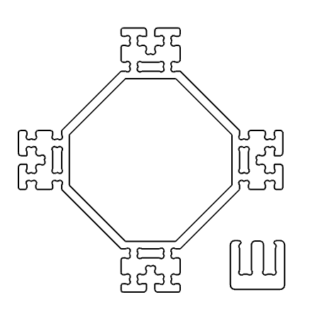
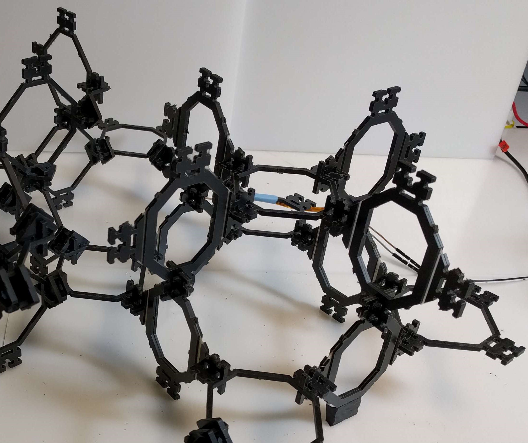
Building a custom end effector to interface with the cells provides several advantages that are not available with the Robotiq Gripper. Principal among these is passive orientation control. Unlike the styrofoam cubes used in the cube-stacking routine, the cells of our material interface with one another with specific interlocking feature. These features provide the structural integrity that allow our material to be an ultra-performance material—having significantly higher strength to weight ratio than naturally occurring materials.
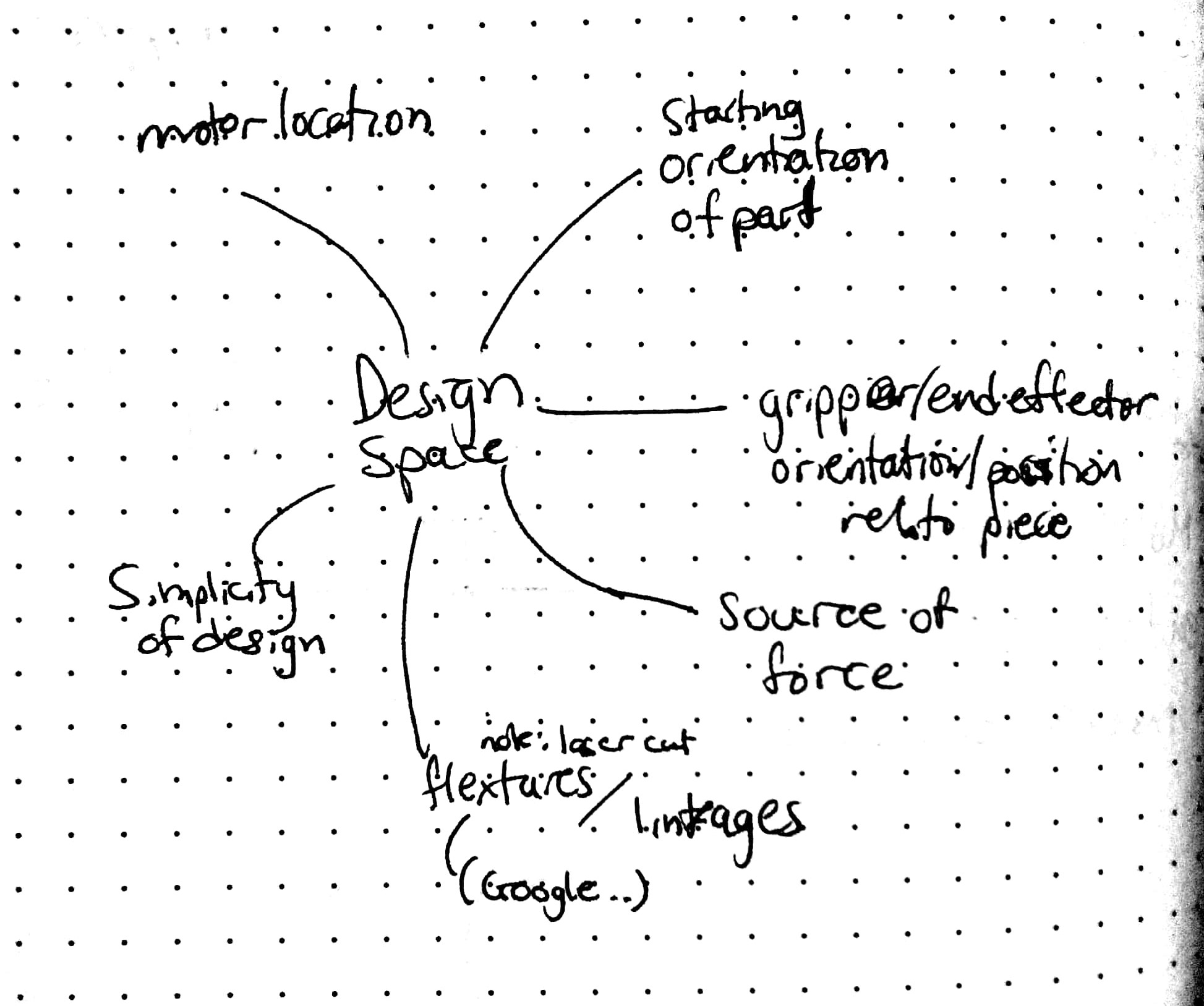
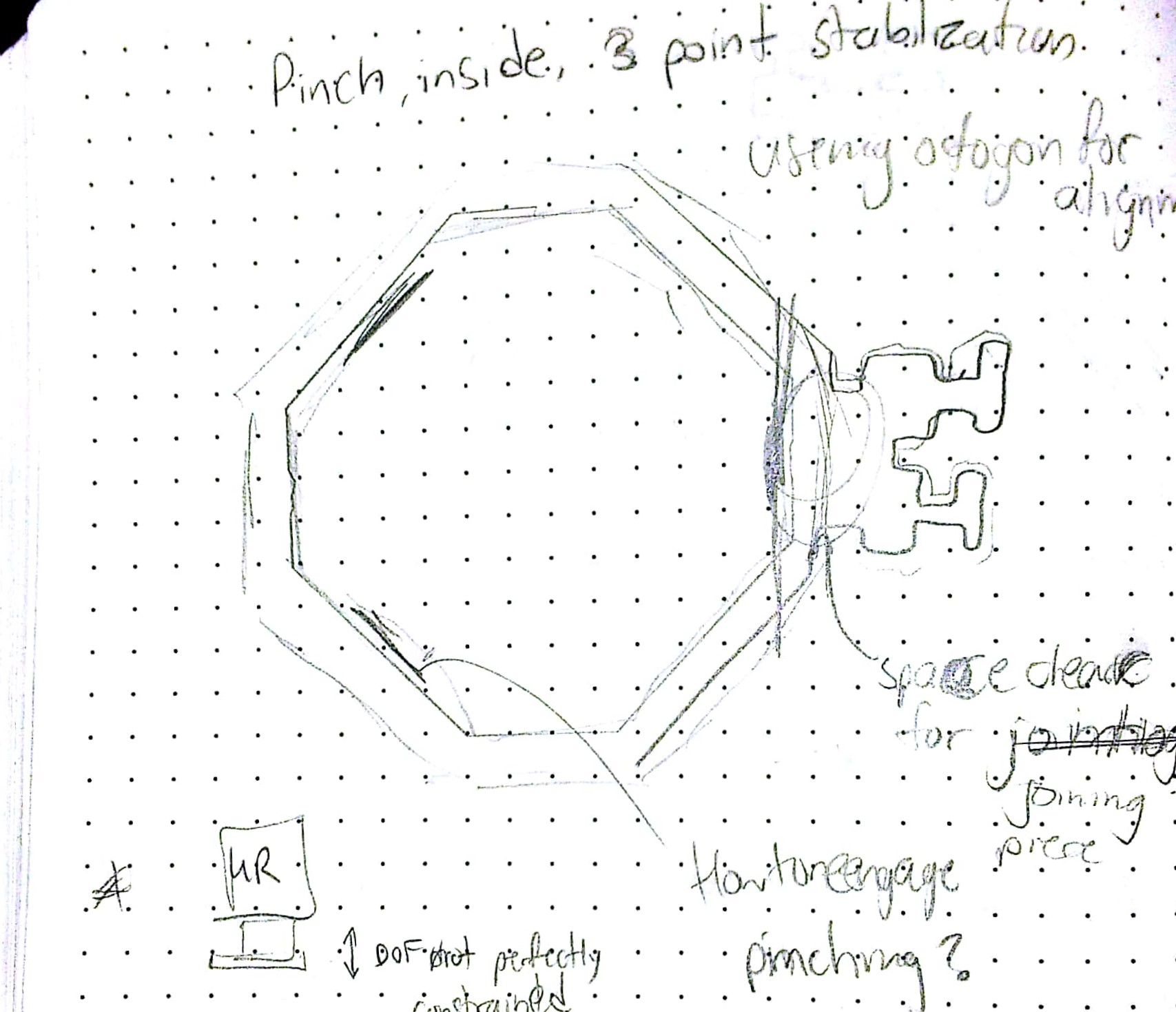
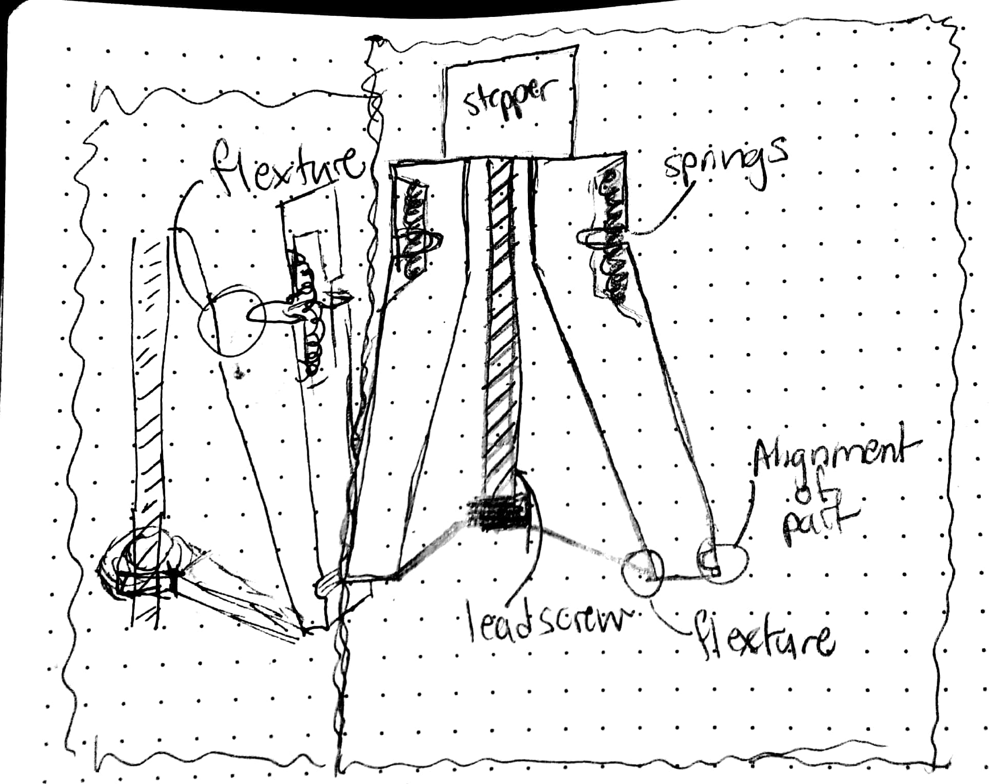
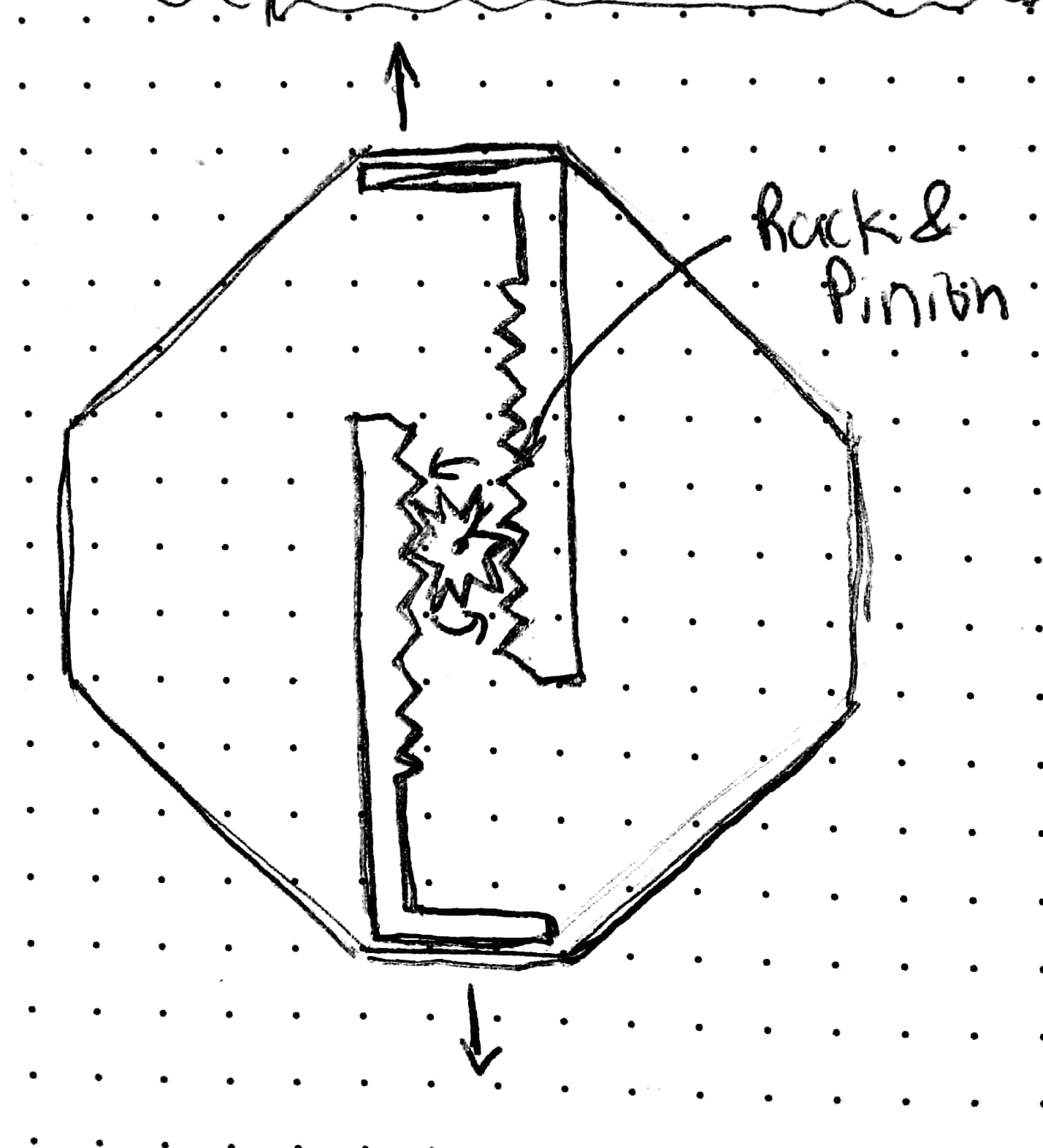
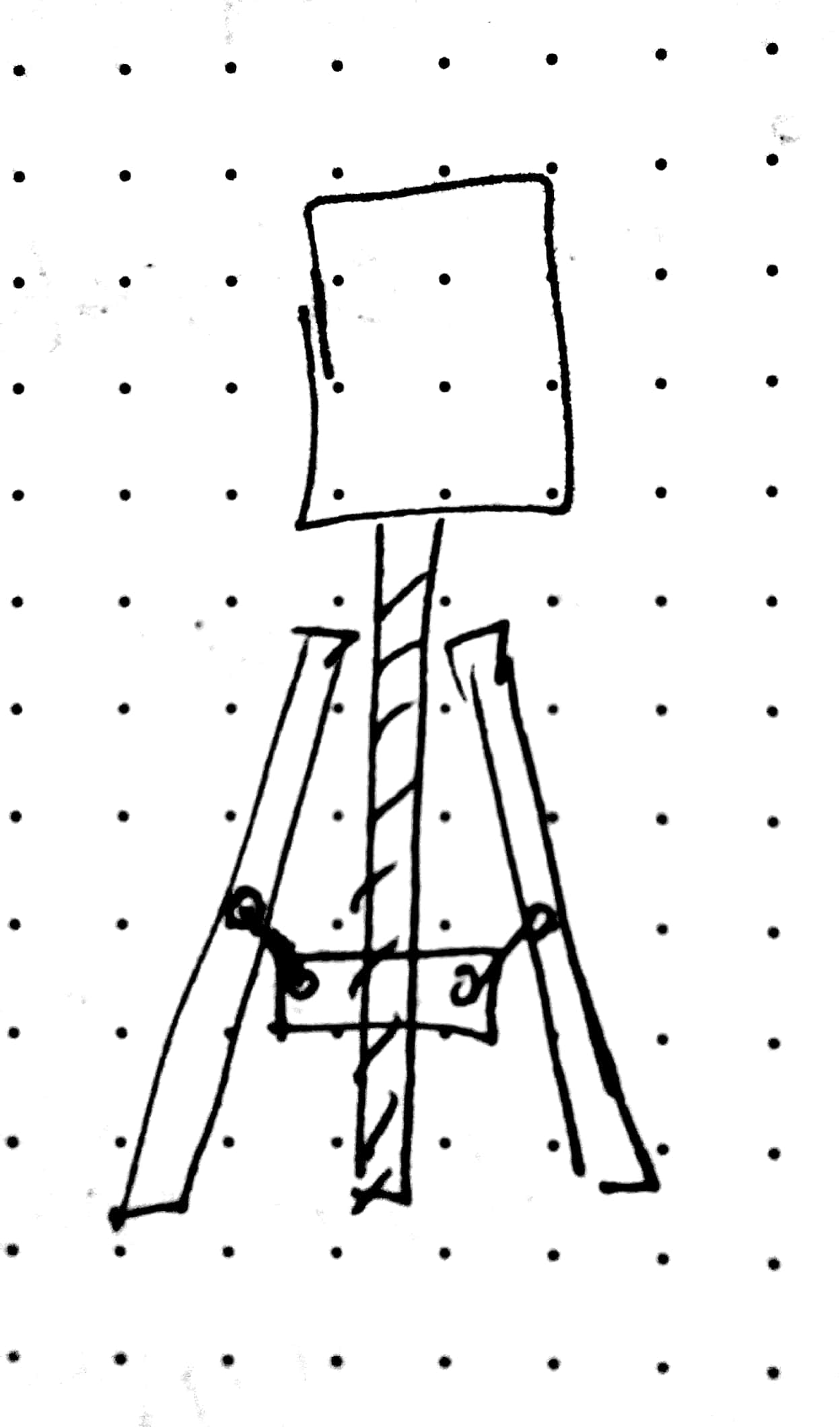
Brainstorming concepts for the end effector produced a decent number of varied designs. Next, I moved onto CADing a few of the concepts.
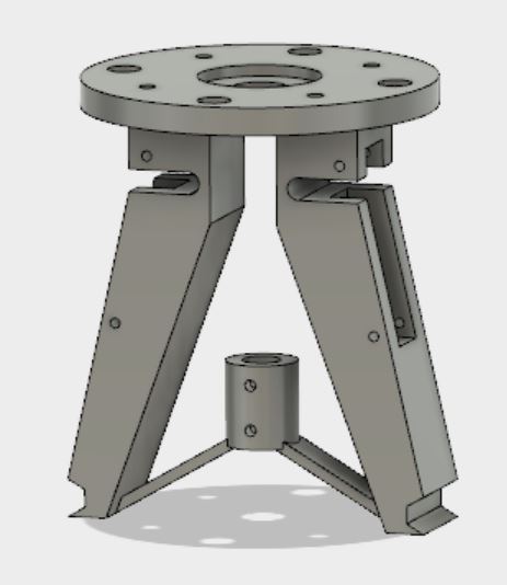
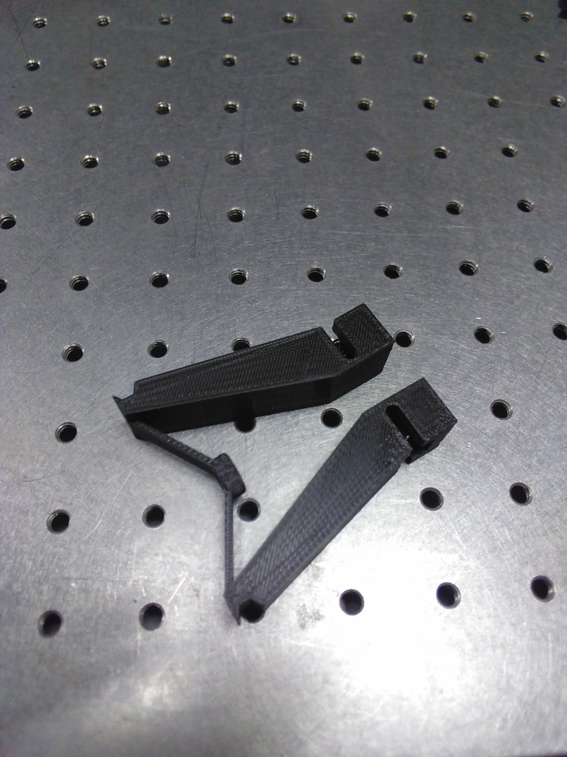
For the final design of the end effector we chose the flexure design primarily for the simplicity of the design. Utilizing the compliance of the 3d-printed materials in this design eliminates the need more complex interfaces such as linkages and bearings. The design of the flexure is dimensioned to allow for sufficient travel to grab and then retain the cell. The section of the flexure end effector which directly interacts includes a bevelled edge to facilitate pickup from a flat surgace. Additionally, the design of the groove allows the end effector to passively correct the orientation of the cell(so that we can locate the cell's interlocking geometry).
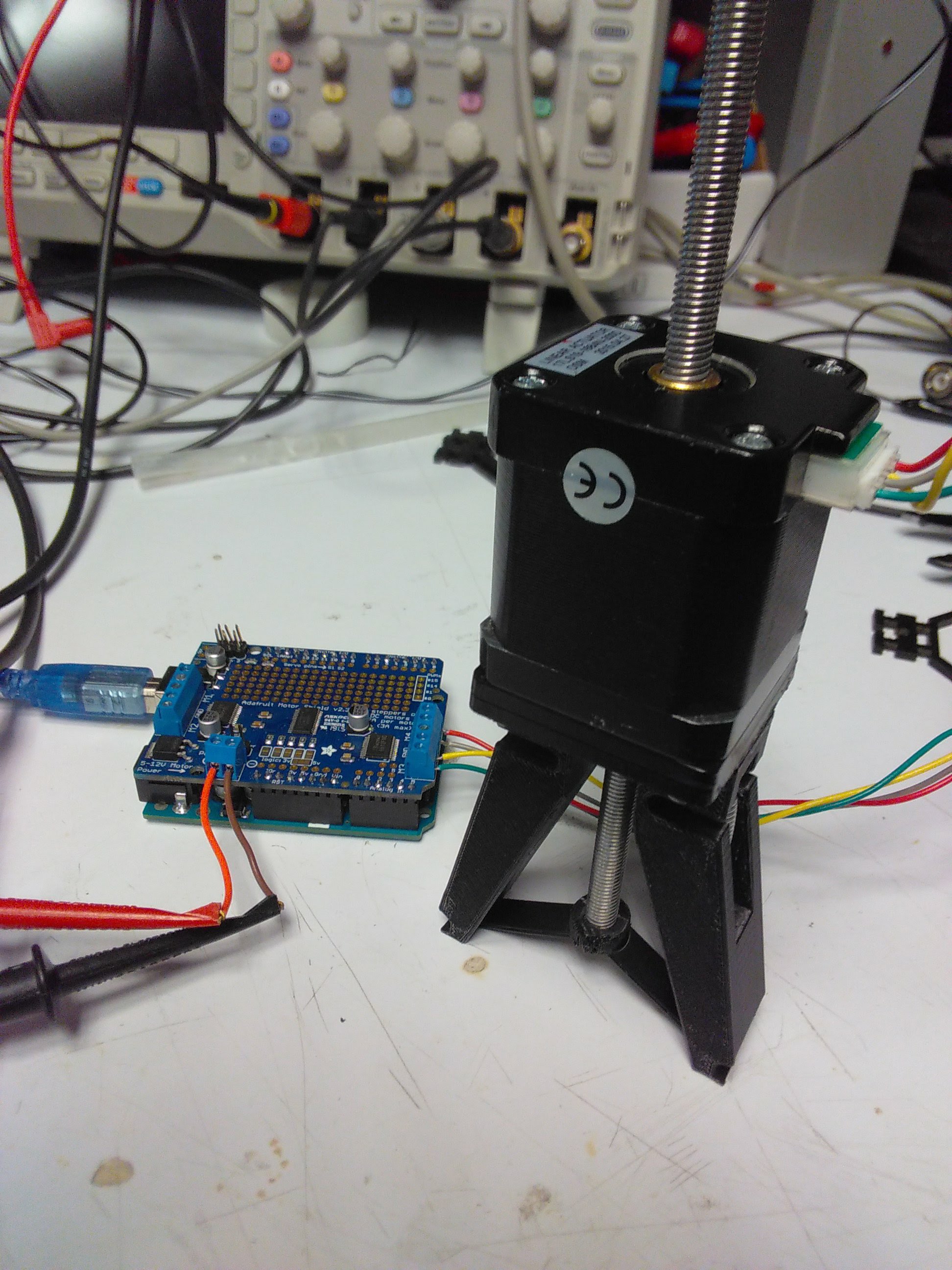
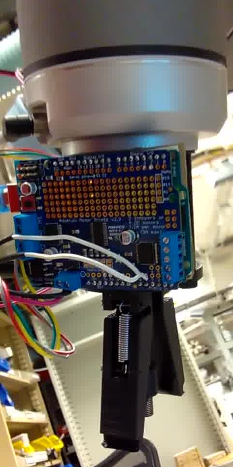
Actuation of the flexure if handled by an arduino which is also mounted to the UR10 robot arm. The Arduino is running a simple program which listens to the status of 2 pins and send the corresoponding PWM signal to a stepper controller(which then actuates the stepper). Using 2 digital pins allows for 4 distinct states necessary for the manuever to grab or release the cell.
We successfully integrated operation of the custom end effector and arm movement all via the terminal!! While this is not a complete demonstration of an automated assembly this shows the integration of many of the essential components needed for an automated assembly for our ultra-performance material. All in all this was a fun project and it was definitely a learning experience.
Future Work
Next steps for the project would to be fine tune the position control of the robot arm via the terminal, while I was able to control movement of the arm I did not achieve the precision necesarry for assembling cells with tightly toleranced interlocking features. The end-effector design works, but the electronics needed to actuate the flexure can definetely be less bulky by building a custom circuit board for the core components. Lastly, the specific routing for assembly is intially very similar to the cube-stacking routine, however, we quickly encounter scenarios in assembly which recquire the cells themselves to flex. This could mean that more work needs to be done in finding a functional routine or it could mean a potential redesign for the cells themselves.